Designing the Smallest Computer in Minecraft
Introduction
Since redstone's introduction to Minecraft made computers in game possible their design has mostly gone one direction, growing faster, more capable, and primarily larger. While a computer that can run its own 3d render pipeline in game is impressive, the fact that it will take up a million blocks and lag your computer to death makes it a somewhat of a self defeating activity. What is the point of making a computer in Minecraft if a normal player would never be able to build it in their world? So when I decided to make my own computer I set out to create the exact opposite, build the smallest turing complete Minecraft computer possible. My goal was to design a computer simple enough that it could be reasonably built in survival, fit in a reasonable footprint (approximately a chunk), and be able to be easily reprogrammed to handle a variety of logical tasks.
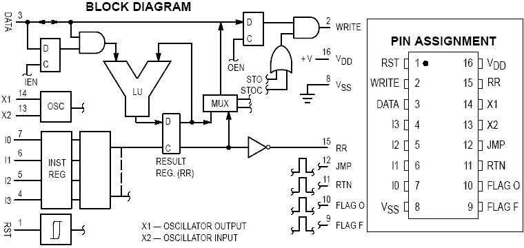
When I first set out on this project the first place I searched for inspiration was the past. After all, the computer engineers of the 60's and 70's were also dealing with similar problems of having extremely limited space and complexity budgets. Looking back through the history of some of the simplest and cheapest chips of the 70's I came across the the aptly named MC14500B. The MC14500B is absurdly simplistic by todays standard, boasting a 4-bit ISA, and a simple 1-bit register it is only capable of a handful of logical operations and a couple of options for control flow, but yet it was just enough to replace old bulky relay logic systems in the 70's.
The idea of a 1-bit logic controller based computer fit Minecraft perfectly. In Minecraft we are operating under very similar constraints Motorola faced in the 70's when producing this chip. Memory is expensive, wide busses are awkward, and for most simple practical tasks you only need a little bit of binary logic. Of course I could not just copy the MC14500 and call it a day, while the MC14500 was the perfect place to draw inspiration, on its own it was not even close to a full computer. Part of its simplicity was eschewing everything but the bare minimum, relying on the designer to provide what they needed in program memory, instruction control flow, I/O was handled. All of these I would need to implement on my own, in a way that was particularly ergonomic with Minecraft mechanics.
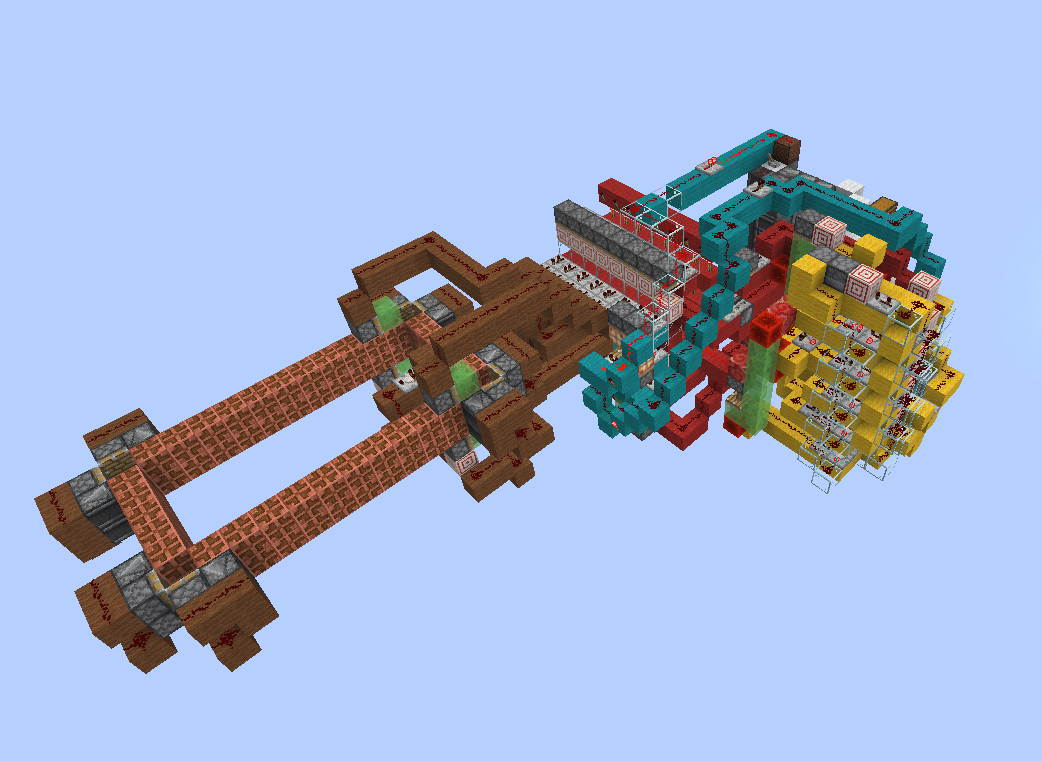
After a few weeks of work and many iterations this idea would finally come into being as the MC^2, short for MineCraft MicroController, a 1-bit Harvard architecture computer with a 4-bit music disc encoded ISA, 8 ports of I/O, just enough control flow and binary logic to handle some small farms and be turing complete while fitting in a footprint barely larger than a chunk.
Capabilities
The MC^2 is not a powerful computer by any means, but its 1-bit ISA is more than enough to handle a variety of simple tasks. Its features include:
- 4-bit music disc encoded instruction set with 15 instructions
- 1-bit internal register
- 8 I/O ports for interfacing with peripherals
- 2 1-bit flags for control flow and state
- Optional tape memory unit for turing complete operation
- 14 game tick (0.7 second) clock cycle
- 1458 instruction program memory (182 bytes)
- Compact footprint of 14x12x17 blocks (excluding the tape memory unit)
- Optional infinitely expandable tape memory unit for data storage
Below can be seen a simple demonstration program that sums two 4-bit numbers together on the tape memory units, outputting the resulting binary number on one of the input lines, and zeroing the other:
Design Overview
At its core the MC^2 is an incredibly simple design: a single 1-bit register, a 4-bit instruction set, a few configurable I/O lines, and some working memory implemented as a kind of moving tape. If you were doing this on an FPGA it would be a nice little final-project CPU build. In Minecraft, the real challenge is making it small without making it useless.
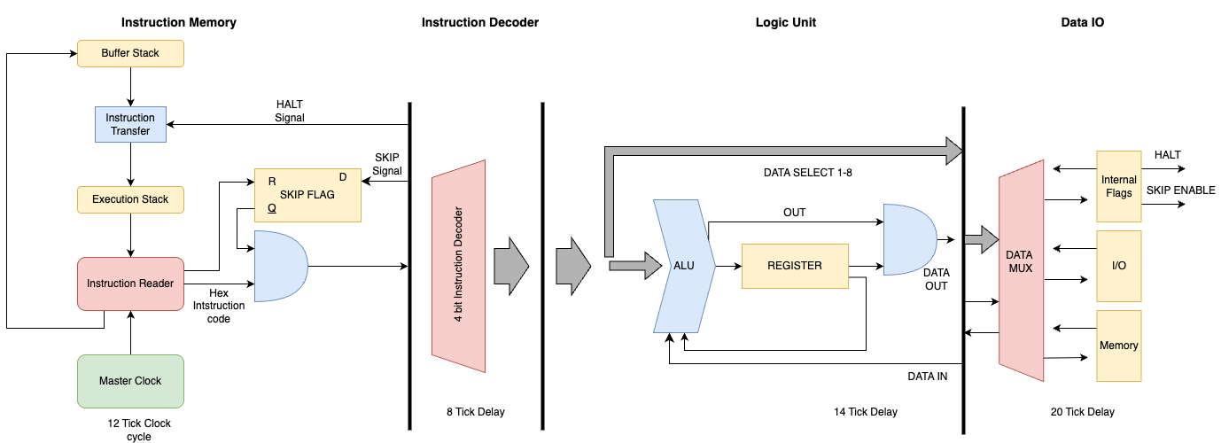
I ended up breaking it down into five core pieces, each of which came with their own design challenges and tradeoffs:
- Instruction Memory – dense, fast program storage using jukeboxes and shulker boxes.
- Decoder - Takes the redstone signal from the jukebox and decodes it into a set of control signals.
- Logic Unit – the part that actually executes the 1-bit instructions.
- I/O – handles the interface between MC^2 and the outside redstone world.
- Tape Memory – a shiftable strip of bits for data storage, essential for turing complete operation but can be eschewed for more I/O
Instruction Memory
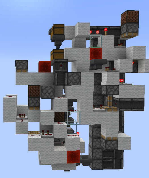
One of the biggest challenges was the implementation of efficient instruction memory. In most Minecraft computers the program ROM is the simplest part, just design a single selectable memory unit and tile it until you run out of space. However that solution would not work under our space constraints, where a traditional ROM design would take up our entire foot print to store just a couple of bytes. Luckily Mojang recently gave us the perfect tool to solve this memory issue, the Jukebox Decoder. The jukebox gives us an efficient way of creating an extremely dense ROM unit, as each music disc encodes a unique redstone signal strength between 1-15 when played, corresponding to a single 4-bit instruction per disc (we are missing a 0 strength disc but 15 instructions is more than enough for our design).
This allows us to store the entire program as a series of items in a chest, giving us an extremely dense form of program memory. However there are no free lunches, and there is good reason that, as far as I am aware, this is the first computer design I have seen that utilizes "disc memory" for the program memory. The problem with this design is that minecraft the only way to push or pull items from a chest is by using a hopper, which do not operate like any normal data structure in how they handle the order of items. Hoppers will always pull out the first item in chests, and will always push items into the first available slot in a chest, however when a item is pulled out, it does not "move" all the subsequent items up in queue, instead the item that was pulled out is simply replaced with an empty slot. This means that as long as the chest is fully emptied before the any items are inserted then it acts as a simple FIFO stack type structure, however if the chest is not fully emptied before the next item is inserted then the items will be out of order, and the program will not run correctly.
The unusual nature of this memory imposes two large design constraints on the computer. First is that our memory is not random-access, we can only read instructions in the order that the program was written in. That means that we have no jumps in our program and it must be fully run to the end before it can loop back to the start or terminate. Second is that we must have a buffer chest to store all the instructions that have already been executed as we cannot simply loop back items into the same chest. This buffer must only empty when we are sure that the program chest is fully empty, otherwise we will end up with a corrupted program.
These two constraints result some of the most important design decisions in the rest of the computer, and in particular the implementation of our instruction memory unit. The heavily limited control flow from the lack of ability to make arbitrary jumps means that instruction predication is the only way we can implement any kind of conditional logic. The need to implement some sort of predication (a conditional skip instruction) is the strictest timing constraint in our entire design, and as such the instruction memory must be design around that timing constraint.
Conversely, as we are only able to read instructions in a linear order, besides the predication instruction there is no need to assume that any instruction will causally affect the execution of future instructions. This means we can heavily pipeline our entire design as by the very nature of our memory we can never have a branch miss. This means that besides the skip instruction, we can afford to have a very long instruction latency, circumventing one of the biggest issues with Minecraft computers, the slow latency of redstone.
The sum result of these restrictions and design choices is a set of four key components that make up the instruction memory unit:
- Shulker Loaders and Unloaders – compact, sequential program storage and transfer.
- Reset Routine – Logic and timing to ensure that the program resets cleanly without corrupting.
- Skip Logic – provides conditional execution through predicated instruction skips.
- Master Clock – the global heartbeat that synchronizes and paces execution.
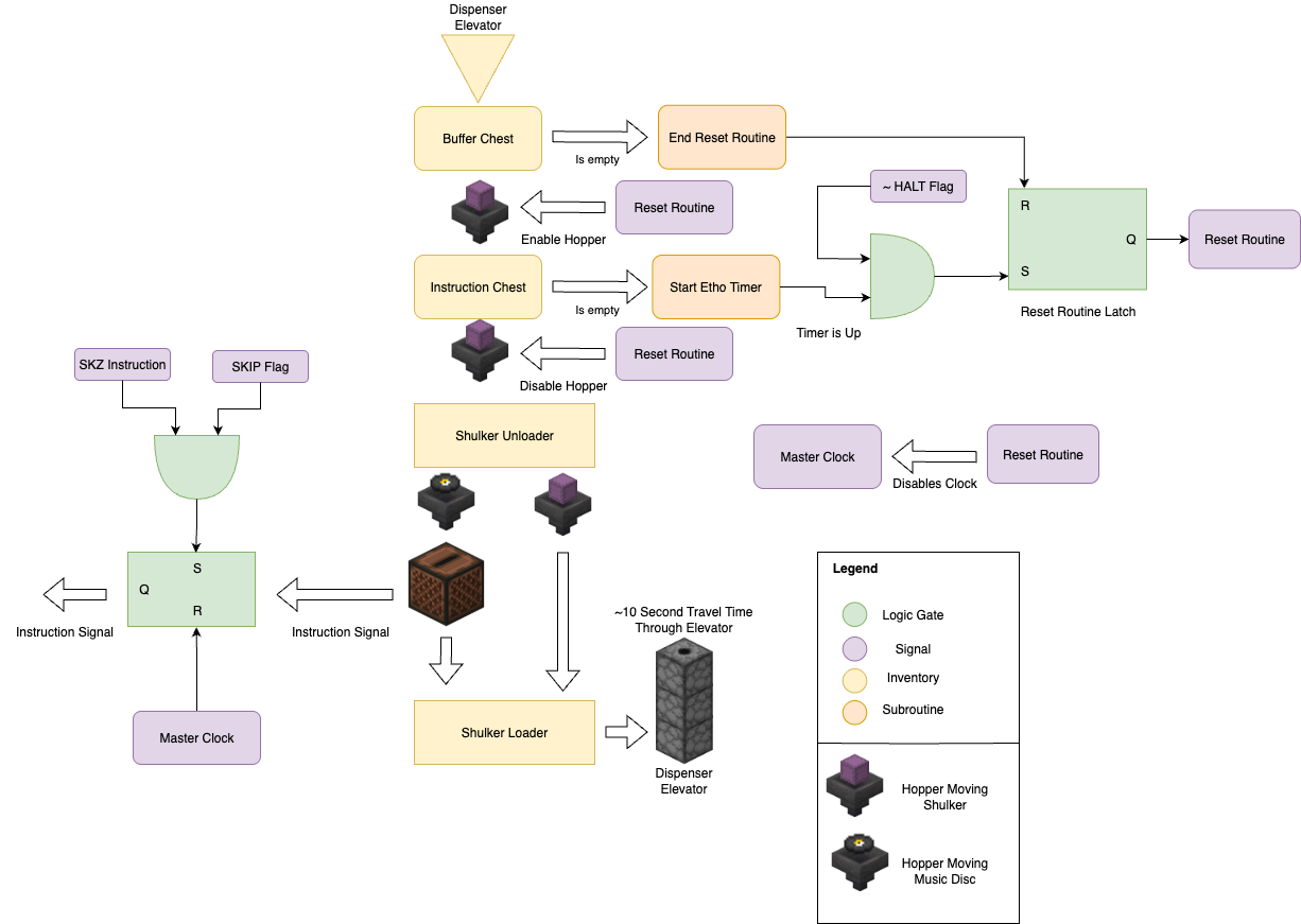
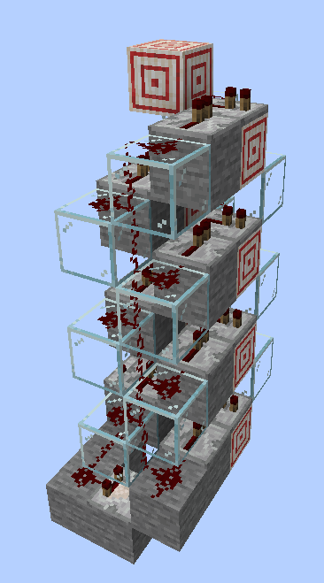
Shulker Loader & Unloaders
The shulker loader and unloader were some of the most essential components of the instruction memory unit, and luckily also the one component where I could draw from past designs. The shulker loader and unloader are responsible for unloading the music discs encoding instructions from a shulker into the jukebox, and then reloading the used discs into a new shulker. This has two main advantages, first it greatly increases our program memory capacity, as each shulker can hold 27 discs, and a double chest of instructions can hold 54 shulkers, giving us a total program memory of 1458 instructions or 182 bytes, which is enough for most simple programs we would want to run. Second it significantly speeds up resetting the program once it has already been run as we can move the shulkers instead of individual discs making the throughput of the reset routine 27x faster than the program execution speed. If the program was not using shulkers then the reset routine would take approximately equal time to run as the program itself as both would be rate limited by the same fixed hopper speed.
The shulker loader and unloader also introduce a couple of restrictions on the program design. First is that as we only send a shulker box back up to the buffer chest when it is full our program must be a multiple of 27 instructions long. This is not a big restriction as we can simply write the assembler to automatically pad out the end of the program with Nops to the next multiple of 27. Second is that as we only track the number of shulkers in the program storage chest for when we need to reset the program, we need to add in a delay to the reset routine to ensure that the last shulker has fully unloaded before we start the reset routine. This requires the addition of some extra timing and logic to the reset routine, which I will discuss in the next section.
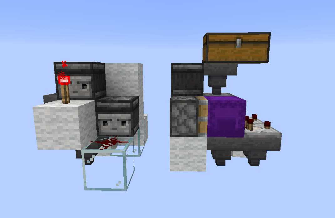
The design of the shulker loader and unloader itself was taken from a great video by KaleHameron. These designs are somewhat standard in the redstone community and are close to optimal in terms of size and speed.
Reset Routine
One of the biggest challenges in the design of the instruction memory was the reset routine. The reset routine is responsible for all the logic and timing ensuring that when the program reaches the end it can be cleanly reset back to the start without corrupting the program. There were a few key challenges that needed to be solved in the implementation of the reset routine.
First is ensuring that the entire program has been fully executed before starting the reset routine. This is particularly important and difficult as the instruction memory is heavily pipelined, meaning that even when the last set of instructions leaves the program chest there will still be a significant delay before it is executed as it makes its way through the shulker unloader, jukebox, loader, and hopper elevator back to the buffer chest. This means that we cannot simply start the reset routine as soon as the program chest is empty, as there will still be instructions in flight that have not yet been executed. To solve this an "Etho clock" style delay was added to the reset routine, which start a fixed delay once the program chest is empty clocked by the limited throughput of a hopper. The advantage of using this sort of timer to delay the reset routine is that is very compact and extremely adjustable compared to a traditional redstone repeater based delay. The disadvantage is that it takes an equal amount of time to reset as the programmed delay. As there are 54 instructions at any one moment inside the pipeline, this means that we have a minimum program length of at least 5 shulker boxes (135 instructions) to ensure that we have enough time to fully allow the Etho clock to reset itself before the program chest is empty. This is not a big restriction as most programs will be much longer than this minimum length, and if they are shorter they can either be repeated, or padded out with NOPs.
Second is properly moving the program discs from the buffer chest back to the program chest without corrupting the order. As mentioned before hoppers do not behave like a normal queue data structure, and only preserve the order of the instructions as long as we do not pull any items out of the program chest while we are inserting items into it. This means that we need to have a flip-flop to ensure that we are either in "insert mode" or "remove mode", and never both at the same time. This is accomplished by using a S-R latch to control two separate hopper lines, one for inserting items into the program chest, and one for removing items from the buffer chest. The latch is set to insert mode by the Etho clock after the program chest if fully empty, and is only reset to remove mode once the program chest is fully full again. This ensures that we never pull items out of the program chest while we are inserting items into it, preserving the order of the instructions.
Skip Logic
The skip logic is one of the most important components of the instruction memory unit, as it provides the only form of conditional execution in the entire computer, but also relatively simple in its design. The skip logic implements a single instruction, SKIP, which will skip the next instruction if the current value in the SKIP flag is 1. This allows us to implement simple control flow in our programs while taking advantage of the heavily pipelined nature of our design. The skip logic is implement using a simple AND gate hooked up to a S-R latch. When the SKIP instruction is executed it sets the latch if the SKIP flag is 1, which will then block the next instruction from being loaded into the logic unit. The latch is then reset once the next instruction has been skipped, allowing normal execution to continue.
The largest challenge with the skip logic is ensuring that the timing is correct, as we need to ensure that the SKIP instruction is fully executed before the next instruction is loaded. This is accomplished by minimizing the latency of the skip logic as much as possible, ensuring that there is the shortest possible delay between the SKIP instruction being executed and the SKIP latch being set. Luckily the skip logic is one of the few components that has a latency constraint, besides it and the delay between the logic unit and updating the internal 1-bit register, there are no other strict timing constraints in the entire design. This allows us to heavily pipeline the entire design, allowing for a very long instruction latency without any risk of branch misses (as we have no branches).
Master Clock
The master clock is the global heartbeat that paces the entire computer, and also is the most simple in design. As aforementioned, there are very few timing requirements imposed by our design due to our limited control flow, and timing requirements that are there are restrictions on maximum clock rate. This means that we can use a relatively fast clock to pace the computer, with only 14 gamet icks (0.7 seconds) between each clock cycle. This is fast enough to make the computer feel responsive while still being slow enough to allow for the longest possible instruction latency without any risk of timing issues. This can be implemented with a simple observer clock, which is very compact.
Decoder
Once the instruction signal leaves the jukebox it needs to be decoded into a set of 15 control signals, one for each instruction in the ISA. This is a slightly more complex task than a simple binary decoder as the jukebox signal is not binary, but instead is a single redstone signal with a strength between 1 and 15 (analogous to an analog signal). This means that we need a specialized decoder known in the redstone community as a "redcoder" to decode the signal. The redcoder works by using two parallel redstone lines, one with the signal strength 1-lower than the other, each of which decreases in strength by 1 for each block of redstone dust it travels over. By looking at the 1 place where one line is on and the other is off we can determine the signal strength.
Luckily redcoders are a well known design in the redstone community, and particularly compact designs specific for fast readout from jukebox encoders have been developed. The design used in the MC^2 is based off of a design by Jazzired used for his Jukebox encoded music machine. This design is close to optimal in terms of size, speed, and latency, and is the best design I have found for this purpose.
Logic Unit
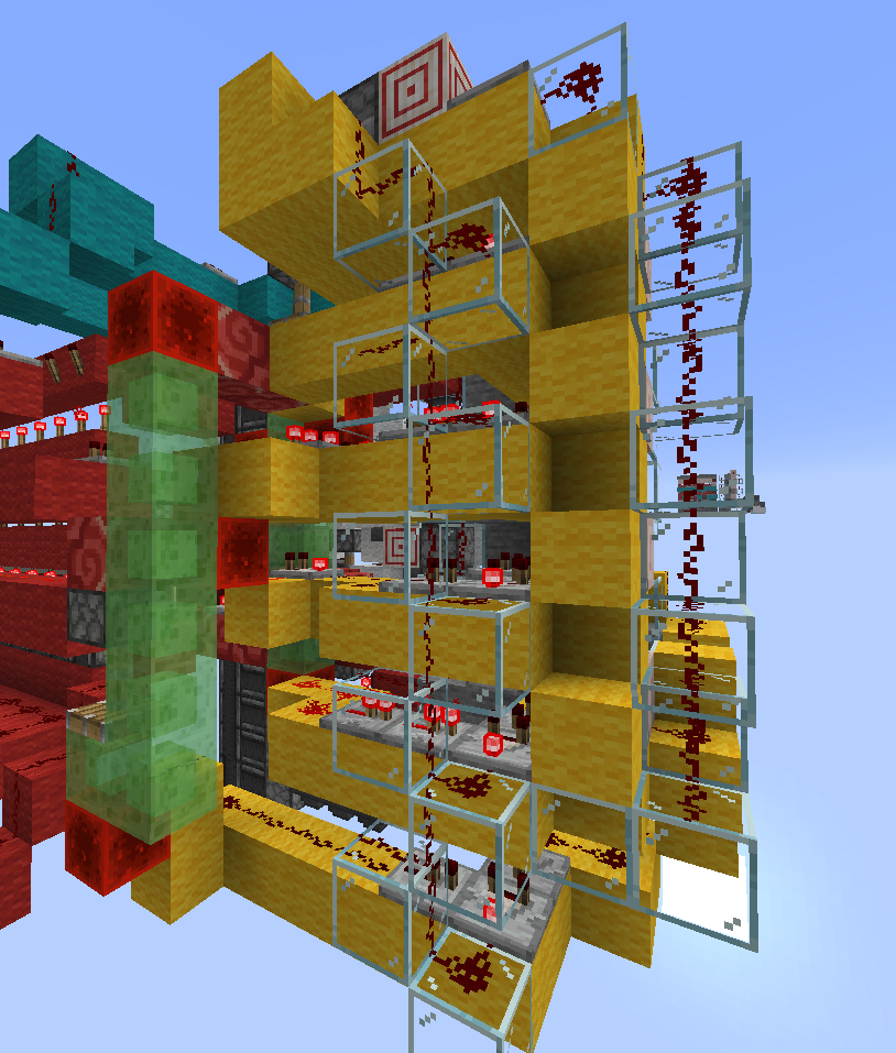
Compared to the complex instruction memory unit the logic unit is relatively simple, it only needs to implement a handful of well known 1-bit logical operations (AND, OR, NOT, XOR) and a few simple data operations (LOAD, OUT), and the 1-bit internal register. The biggest challenge in the logic unit was timing as the logic unit needs to make sure the executed instruction has fully propagated within 14 game ticks (0.7 seconds) before the next instruction is executed. To ensure this the logic unit was designed to have a fixed latency for all instructions, with each instruction sharing as similar a path through the logic unit as possible. This was accomplished by breaking the logic unit into a series of stages, each of which adds a fixed amount of delay to the signal. Each instruction then takes a path through the logic unit that has the same number of stages, ensuring that all instructions have the same latency. This also has the advantage of simplifying the timing analysis of the logic unit, as we only need to ensure that the longest path through the logic unit is less than 14 game ticks. The disadvantage of this design is that it adds some extra delay to some instructions that could be executed faster, but ultimately this does not matter as we are still limited by the 14 game tick clock cycle.
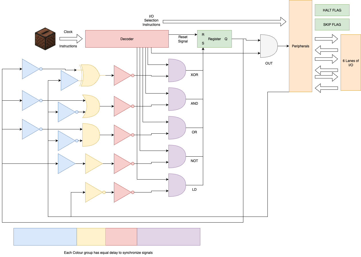
Slimestone tower
One particularly innovative solution I found for making the logic unit as compact as possible was to use a tower of slime blocks and redstone blocks to vertically transmit the signal downwards. The slime blocks allow the redstone blocks to be moved up and down by a piston, allowing us to transmit the signal downwards on a fixed delay for all vertical levels. This also has the advantage of lacking the directionality of solutions like a stone wall observer or glass tower, both of which can only transmit the signal in one direction. The slime block tower allows signals to be transmitted from both the top and the bottom, allowing for a more compact design. The slime block tower also greatly simplifies the logic as by moving the default position of the redstone blocks up and down we can add in an inversion to the signal for free, giving me greater versatility in the logic design while keeping the timings synchronized and the design compact.
I/O
The I/O unit is responsible for interfacing the MC^2 with peripherals and the outside world. Due to the simplicity of the logic unit the I/O unit uses a relatively unusual method of addressing. Whereas in a normal computer the I/O would be addressed by some operand in the instruction, instead in the MC^2 the I/O is addressed by a set of 8 different unique instructions, one for each I/O port. This sort of unary addressing is not common in modern computers as it is inefficient in terms of instruction space, however in the MC^2 it is a good tradeoff as it allows us to have more logical instructions available in the 4-bit instruction set, while still having a reasonable number of I/O ports without the need to implement a more complex instruction memory which can handle operands.
The I/O unit itself is relatively simple, each I/O port is a piston based S-R latch which allows signals to travel to 2 different lines shared between all ports, one for input and the other for output. Each S-R latch is reset whenever an I/O instruction comes in, and the a single one of the latches is set by the output of the decoder. This allows us to have a simple and compact I/O unit that can handle a reasonable number of I/O ports without the need for complex addressing or multiplexing.
On top of this addressing scheme the first 2 I/O ports are taken up by additional execution flags, the SKIP flag and the HALT flag. Bott are implemented as S-R latches which can be set and reset by the I/O instructions. The SKIP flag is used by the skip logic in the instruction memory to determine whether to skip the next instruction, while the HALT flag is used to stop the computer from executing any further instructions once it reaches the end. However, both flags can also be externally accessed by peripherals and read by the program, allowing for them to be used additional "scratch" space for simple programs where they are not immediately needed for their primary purpose.
Tape Memory
While the MC^2 does not need any working memory for simple logic controller type uses, an infinitely expandable tape and persistent memory is essential for turing complete operation. For this I implemented a simple tape memory unit peripheral which can be addressed though the standard I/O instructions. The tape memory unit is implemented as simple feed tape of copper bulb which can be shifted left or right by one bit at a time, and the active bulb be read and written to from the MC^2 through the I/O instructions. The tape memory unit is not strictly necessary for the operation of the MC^2, and can be eschewed for more I/O ports if desired, however it is essential for turing complete operation and allows for more complex programs to be written.
For turing complete operation the remaining 6 I/O ports are used to interface with 2 separate tape memory units, one for program state, and the other to track where we are in the program and to be used as scratch memory. Without the tape memory unit the MC^2 by default only has 3-bits of persistent state, the internal 1-bit register, and the 2 1-bit flags. This is not enough to properly implement branching or loops, as when the program loops back to the start it will lose all state. With the tape memory unit we can store additional state on the tape, allowing for more complex programs to be written with complex branching implemented through predication and state stored on the tape, which is accessed each loop through the main program. While this could be implemented all on one tape memory unit, having two separate tape memory units allows for a more compact design as the tape needs to be shifted left and right 1 bit at a time, so minimizing the number of shifts between different regions in memory on 1 tape by splitting it into 2 separate tapes makes the program more efficient.
Programming
Now that we have a working computer design, the next step is to actually be able to program it. As previously mentioned compared to a traditional computer the limitations of the instruction memory impose an unusual challenge for our programming model. Being limited to only 4-bits means we use operand-less instructions, and can only access I/O or peripherals through dedicated instructions. The lack of random access memory means we can only read instructions in a linear order, resulting in a lack of jumps and the need to implement all control flow through predication. Finally for turing complete operation we need to implement some sort of working memory through a tape memory unit which only lets us read and write 1 bit at a time, and shift the tape left and right. All of these limitations make for an unusual programming model that is difficult for humans to write directly requiring a specialized assembler to make programming feasible.
Instruction Set
| Number | Binary Op Code | Instruction | Music Disc |
|---|---|---|---|
| 1 | 0001 | XOR | 13 |
| 2 | 0010 | SKZ | cat |
| 3 | 0011 | AND | blocks |
| 4 | 0100 | LD | chirp |
| 5 | 0101 | OR | far |
| 6 | 0110 | OUT | mall |
| 7 | 0111 | NOT | mellohi |
| 8 | 1000 | DA1 | stal |
| 9 | 1001 | DA2 | strad |
| 10 | 1010 | DA3 | ward |
| 11 | 1011 | DA4 | 11 |
| 12 | 1100 | DA5 | wait |
| 13 | 1101 | DA6 | Pigstep |
| 14 | 1110 | DA7 | otherside |
| 15 | 1111 | DA8 | 5 |
The MC^2s instruction set is relatively simple and can be broken up into an handful of categories:
- Logical Operations: XOR, AND, OR, NOT
- Data Operations: LD (load), OUT (output)
- I/O Operations: DA1-DA8 (data in/out to I/O port 1-8)
- Control Flow: SKZ (skip if zero)
While most of these can have their operation intuited from the design, I think it is useful to go over their exact functionality and how they interact with the internal state of the computer.
Logical Operations
The logical operations are the core of the MC^2s functionality, allowing us to perform basic binary logic on the internal 1-bit register and the input line. The logical operations are all standard 1-bit logic gates, with the exception of NOT which simply inverts the internal register. All logical operations have the same latency, and all update the internal register within 1 clock cycle, imposing no additional constraints on their programming (this feature is not shared with some of the other instruction).
Data Operations
The data operations allow us to interact with the internal 1-bit register and the input/output lines. The LD instruction loads the value from the input line into the internal register, while the OUT instruction outputs the value of the internal register to the output line resulting in a pulse. Both of these instructions have the same latency as the logical operations and similarly have no special timing constraints.
I/O Operations
The I/O operations are probably the most unusual aspect of the ISA due to our operand-less instruction design. Each I/O operations does two things, first they reset all the I/O latches, and then they set a single I/O latch corresponding to the I/O port being addressed. Each I/O port therefore corresponds to a paired input and output line, which is useful for interfacing with peripherals. All the I/O ports are the same besides the first two, which are reserved for the SKIP and HALT flags.
The SKIP and HALT flags can be read and written to like normal I/O ports with the added functionality of having internal memory which remembers and saves the last written value in a register. The SKIP flag is used by the skip logic to determine whether to skip the next instruction, while the HALT flag is used to stop the computer from executing any further instructions once it reaches the end. Both flags can also be externally accessed by peripherals and read by the program, allowing for them to be used additional "scratch" space for simple programs where they are not immediately needed for their primary purpose. Both flags also have significant latency in having their value updated to it being seen by the components that use them, this requires appending any update to the SKIP or HALT flag with a NOP instruction to ensure that the value is properly updated before it is used. In practice this does not add much overhead as the flags are not updated often in most programs. The delay on update only applies to if they are used as flags, if they are used as scratch space then they can be used immediately after being written to.
The HALT flag is especially useful as scratch space as its value is only checked once at the end of the program, meaning that it can be used as temporary storage without affecting the program flow. The SKIP flag on the other hand is checked before every instruction, meaning that it can be used for more complex control flow, but also means that it cannot be used as temporary storage without affecting the program flow if SKZ instructions are being used. Additionally as the HALT flag is externally accessible it can be used to remotely start and stop the computer, acting potentially as a watchdog timer or external control signal.
While the I/O was designed to interface with many sorts of custom external peripherals, the tape memory is the most important for turing complete operation and thus its functionality is worth going over in more detail. The tape memory is implemented as a simple feed tape of copper bulbs which can be shifted left and right by one bit at a time. This is done by having two of the I/O ports being connected to two inputs to the tape memory, one which shifts left it a high signal is received, and the other which shifts right if a high signal is received. These two lines only use the output line of the I/O port and leave the input line free. This is somewhat cumbersome as it means that we must have a high value in the internal register to shift the tape, but values can be easily saved by using the HALT flag as temporary storage, or through a secondary tape memory unit.
One disadvantage of this design is the sensitivity to timing, especially as the tape gets larger. As the tape is shifted by a piston mechanism it takes a fixed amount of time for the tape to fully shift left or right, and if the next instruction is executed before the tape has fully shifted then the wrong bulb will be read or written to. To mitigate this issue a short delay should be added after each shift instruction using a NOP to ensure that the tape has fully shifted before the next instruction is executed depending on the size of the size of the piston tape used.
The read and write functionality of the tape memory is implemented through a single I/O port, which uses the input and output lines of the I/O port to read and write the value of the currently active copper bulb. To read the value of the active bulb we simply use the input line of the I/O port, which will be high if the bulb is on and low if it is off. To write a value to the active bulb we use the output line of the I/O port, which will toggle the value of the active bulb if it is high. This means that to directly save a value to the tape we must first use an XOR instruction on the bulb to make sure we toggle it to the desired value. This is somewhat unusual but it is the simpler solution in terms of hardware design and additionally gives us a free XOR operation which is useful for some arithmetic operations on the tape.
Skip Instruction
The SKZ instruction is probably the most important part of the ISA as it provides the only form of control flow in the entire computer. The logic behind the SKZ instruction is simple, when the SKZ instruction is executed it checks the value of the SKIP flag, and if it is 1 then it skips the execution of the next instruction (intercepting it before it reaches the logic unit). This allows us to implement simple conditional execution in our programs, allowing for basic branching and loops to be implemented through predication. The disadvantage of this design is that when programming by hand it is tedious to write out predicated instructions and essentially doubles the number of instructions and halves the clock speed of the program. However this is a necessary tradeoff to make the computer fit in our small footprint, and with a good assembler the tedium of writing predicated instructions can be mostly avoided.
Note: It may be counterintuitive that the SKZ instruction skips if the internal register is 1 with its name being "Skip zero", this is just a holdover from the MC14500B which had a similar instruction called "Skip on zero" which skipped the next instruction if the internal register was 0. I decided to keep the name for familiarity, but changed the functionality to skip if the SKIP flag was 1 instead of 0 as it made more sense for programming.
Control Flow
While the predictation only control flow model of the MC^2 is somewhat unusual, it is by no means unprecdented. Predication based control flow is common in both modern and historical computer architectures, and is particularly common in GPUs today. In fact the main inspiration for the implementation of complex control flow on this computer, and the feasibility of the entire design came from the x86 MOV only compiler, which similarly implemented complex control flow through only predication and looping from the bottom to the start of the program, and was even abel to implement a full C compiler on top of this limited instruction set.
Similar to the MOVfuscator, the MC^2 also implements control flow through having each branch be conditionally skipped by some value in memory, which at any branch point can be set and checked by the program. The main difference is that the MC^2 does not have a full register file to store values in, and instead must use the tape memory unit to store values. Thus to make this easier for general computation I chose to use 2 separate tape memories. The first is the persistent memory storage space, where all of our working variables are stored. The second is our program counter, this tape memory is used to store binary value (4-bit in my example implementations but theoretically infinitely expandable) which tracks which 'branch' we are in when we loop back to the start of the program. At each possible branch point the program checks the value of the program counter and conditionally sets the SKIP flag to either skip or execute the next batch of instructions. This allows us to implement complex branching and loops through predication, while only needing a single loop back to the start of the program.
For an example of how this works in practice, consider a simple program which has 3 branches, A, B, and C each of which occurs sequentially in our code. At the start of the program we check the value of the program counter, if it is 0 then we set the SKIP flag to 0 and go through all the code in branch A, where each instruction in the branch is predicated with a SKZ instruction. Next the code would move on to branch B, where similarly we check the value of the program counter, if it is 1 then we set the SKIP flag to 0 and go through all the code in branch B, again with each instruction predicated. Finally we move on to branch C, where we check if the program counter is 2, and if so we set the SKIP flag to 0 and go through all the code in branch C. At any point in each of these branches the program can modify the value of the program counter, jumping to any of the branches on the next loop through the program.
Now lets see an actual example of how this would look in practice. Consider the following pseudocode which implements a simple program with 3 branches:
if (state == 0) {
    // Branch A
    doSomething();
    state = 2;
} else if (state == 1) {
    // Branch B
    doSomethingElse();
    state = 0;
} else if (state == 2) {
    // Branch C
    doAnotherThing();
    state = 1;
}
This program can be implemented on the MC^2 in pseudocode as follows:
// Start of program
If state == 0:
    SKIP = 0
else:
    SKIP = 1

SKZ:
  DoSomething() // Branch A code

state = 2

IF state == 1:
    SKIP = 0
else:
    SKIP = 1

SKZ:
  DoSomethingElse() // Branch B code
state = 0

IF state == 2:
    SKIP = 0
else:
    SKIP = 1

SKZ:
  DoAnotherThing() // Branch C code
state = 1

// End of program, loop back to start
While this shows that complex control flow can be implemented through predication, there is an obvious inefficiency in this design. As to jump to any branch we must go through all the previous branches and skip them, this means that the time to jump to a branch is linear in the number of branches. This is not a big issue for simple programs with only a few branches, but for more complex programs with many branches this can become a significant bottleneck. However this is a necessary tradeoff to make the computer fit in our small footprint, and with a good assembler the tedium of writing predicated instructions can be mostly avoided.
Assembler
To make programming the MC^2 feasible I wrote a simple assembler and emulator in C++ which takes in a simple assembly language and outputs a list of music discs which can then be furthered processed by a python script to generate a command which would paste the program into a chest in Minecraft. The assembler itself is relatively simple, but has a few key additional features to make programming less tedious and error prone.
First is the addition of a simple macro system which allows for common patterns to be abstracted away into a single macro which in unrolled into the full set of instructions by the assembler. This is particularly useful as there are both many common programming patterns (such as setting and checking the program counter) and also as previously mentioned branching, and therefore code reuse is especially costly in our architecture (in our case Don't Repeat Yourself is not a good maxim). Having a macro system which unrolls at assembly time allows for code reuse without the runtime cost of function calls or jumps.
In addition to simple code reuse, the macro system on the assembler also allows for recursive macro calls, both using macros inside of macros, as well as having macros be able to take other macros as arguments. This allows for complex patterns to be abstracted away, and even allows for the creation of essentially a higher order language on top of the assembly language. For example setting and checking the program counter can be abstracted away into a single macro which takes a 4-bit value as an argument. The 4-bit value itself is a macro which expands to the appropriate set of instructions to generate that value on the tape memory. This allows for the programmer to think in terms of higher level concepts such as "set program counter to 3" instead of having to think about the low level details of how to actually implement that on the MC^2, with the assembler taking care of the low level details.
For an example of the assembler in action, consider the following simple program which sets both of the tape memory units to 0101:
; Sets the current cell to a 4bit binary value
def set_cell_values(one_val, two_val, three_val, four_val, LEFT, WRITE, RIGHT)
    WRITE
    one_val()
    XOR
    OUT
    index(LEFT)

    WRITE
    two_val()
    XOR
    OUT
    index(LEFT)

    WRITE
    three_val()
    XOR
    OUT
    index(LEFT)

    WRITE
    four_val()
    XOR
    OUT
    HIGH()
    RIGHT
    OUT
    OR ; append those ors in the middle of the outs in order to buffer them to let the tape cycle
    OUT
    OR
    OUT
end

; sets the reg to a high value
def HIGH()
    LD
    XOR
    NOT
end

; sts the reg to a low value
def LOW()
    LD
    XOR
end

; moves the tape in a given direction by the given I/O line
def index(DIRECTION)
    HIGH()
    DIRECTION
    OUT
end

set_cell_values(HIGH, LOW, HIGH, LOW, DA3, DA4, DA5)
set_cell_values(HIGH, LOW, HIGH, LOW, DA6, DA7, DA8)
As you can see the assembler allows for a much more concise and readable way to write program for the MC^2 when the appropriate macros are defined. The ability to have higher order macros allows for essentially a custom DSL to be built on top of the assembly language, allowing for complex patterns to be abstracted away and making programming the MC^2 feasible.
Another bit of syntactic sugar added to the assembler is the ability to use SKZ on entire macros. This allows for entire blocks of code to be conditionally executed based on the value of the SKIP flag, without having to manually add a SKZ instruction before each instruction in the block. This is particularly useful for implementing branches, as an entire branch can be wrapped in a single SKZ macro call, making the code much more readable and less error prone.
Finally the assembler also automatically pads out the program to be a multiple of 27 instructions long, ensuring that the shulker loader and unloader work correctly without any additional effort from the programmer. This is done by simply adding NOP instructions at the end of the program until it is a multiple of 27 instructions long. While there is not any explicit NOP instruction in the ISA, we can use the OUT instruction with a low value in the internal register to effectively act as a NOP, or chain an even number of NOT instructions together to achieve the same effect. These patterns are also useful for adding in small delays in the program if needed.
Example Program
Here is an example of a simple program which sets the value in the first memory tape toa fixed value then decrements it in a loop until it reaches zero, after which the program halts. This program uses both tape memory units, with the first being used as the persistent storage for the current value, and the second being used as the program counter to track which branch we are in. The program increments the value in the first tape memory unit by 1 each loop through the program, and once it reaches the desired value it sets the HALT flag to stop the program from executing any further instructions.
; Increment the 4 bit value stored in the tape
def increment_tape(LEFT, WRITE, RIGHT)
    ; Assume we are starting at the correct starting index
    WRITE ; select the write value
    LD ; Set value in the register to 1
    XOR
    NOT

    OUT ; Toggle value in the tape
    LD ; LD value
    NOT ; if toggled 1-0 then propagate to next bit
    DA2 ; store in DA1
    OUT
    LD
    XOR
    NOT
    LEFT
    OUT;index the tape one to the left

    DA2
    LD
    WRITE
    OUT
    LD
    NOT
    DA2 ; store in DA1
    AND ; if DA1 is high and the value written is high then store high
    OUT
    LD
    XOR
    NOT
    LEFT
    OUT;index the tape one to the left

    DA2
    LD
    WRITE
    OUT
    LD
    NOT
    DA2 ; store in DA1
    AND
    OUT
    LD
    XOR
    NOT
    LEFT
    OUT;index the tape one to the left

    DA2
    LD
    WRITE
    OUT
    LD
    NOT
    DA2 ; store in DA1
    AND
    OUT

    LD
    XOR
    NOT
    RIGHT
    OUT
    OUT
    OUT

end

def decrement_tape(LEFT, WRITE, RIGHT)
    ; Assume we are starting at the correct starting index
    WRITE ; select the write value
    LD ; Set value in the register to 1
    XOR
    NOT

    OUT ; Toggle value in the tape
    LD ; LD value
    DA2 ; store in DA1
    OUT
    LD
    XOR
    NOT
    LEFT
    OUT;index the tape one to the left

    DA2
    LD
    WRITE
    OUT
    LD
    DA2 ; store in DA1
    AND ; if DA1 is high and the value written is high then store high
    OUT
    LD
    XOR
    NOT
    LEFT
    OUT;index the tape one to the left

    DA2
    LD
    WRITE
    OUT
    LD
    DA2 ; store in DA1
    AND
    OUT
    LD
    XOR
    NOT
    LEFT
    OUT;index the tape one to the left

    DA2
    LD
    WRITE
    OUT
    LD
    DA2 ; store in DA1
    AND
    OUT

    LD
    XOR
    NOT
    RIGHT
    OUT
    OUT
    OUT
end

; sets the reg to a high value
def HIGH()
    LD
    XOR
    NOT
end

; sts the reg to a low value
def LOW()
    LD
    XOR
end

; indexes tape in the DIRECTION given
def index(DIRECTION)
    HIGH()
    DIRECTION
    OUT
end

; Sets the current cell to a 4bit binary value
def set_cell_values(one_val, two_val, three_val, four_val, LEFT, WRITE, RIGHT)
    WRITE
    one_val()
    XOR
    OUT
    index(LEFT)

    WRITE
    two_val()
    XOR
    OUT
    index(LEFT)

    WRITE
    three_val()
    XOR
    OUT
    index(LEFT)

    WRITE
    four_val()
    XOR
    OUT
    HIGH()
    RIGHT
    OUT
    OUT
    OUT
end

; checks if the current cell is equal to a value specified, if so leaves register high
def check_equality(one_val, two_val, three_val, four_val, LEFT, WRITE, RIGHT)
    WRITE
    one_val()
    XOR
    DA2 ; store intermediate value in DA1, if any is high it will be high
    OUT

    index(LEFT)

    WRITE
    two_val()
    XOR
    DA2
    OR
    OUT
    index(LEFT)

    WRITE
    three_val()
    XOR
    DA2
    OR
    OUT
    index(LEFT)

    WRITE
    four_val()
    XOR
    DA2
    OR
    OUT
    HIGH()
    RIGHT
    OUT
    OUT
    OUT

    DA2
    LD
    NOT
end

; sets a point which a jump instruction will branch to, encoded by the 4 bit value
; all this does is set the skip flag low if the value in the selected cell equals the described value
def branch_flag(one_val, two_val, three_val, four_val, LEFT, WRITE, RIGHT)
    check_equality(one_val, two_val, three_val, four_val, LEFT, WRITE, RIGHT)
    NOT
    DA1
    OUT
    NOT
    NOT ; this will set skip flag to low only if the value provided is same as the value in the currently selected cell
end

; jumps to the branch flag encded by the supplied 4 bit value on
; all this really does is set cell a a value then skip flag high
def jump_to(one_val, two_val, three_val, four_val, LEFT, WRITE, RIGHT)
    set_cell_values(one_val, two_val, three_val, four_val, LEFT, WRITE, RIGHT)
    HIGH()
    DA1
    OUT
    NOT
    NOT
end


; START OF PROGRAM

;At the start set the cell Value in tape 1 to 1010
branch_flag(LOW, LOW, LOW, LOW, DA6, DA7, DA8)
SKZ
set_cell_values(HIGH, LOW, HIGH, LOW, DA3, DA4, DA5)

; jump to the loop (0001)
jump_to(LOW, LOW, LOW, HIGH, DA6, DA7, DA8)

branch_flag(LOW, LOW, LOW, HIGH, DA6, DA7, DA8)

SKZ
decrement_tape(DA3, DA4, DA5) ; decrement in a loop until reaches zero
SKZ
check_equality(LOW, LOW, LOW, LOW, DA3, DA4, DA5)

SKZ
DA1
SKZ
NOT ; if NOT EQUAL then skip the jump to statement
SKZ

OUT
NOT
NOT

SKZ
jump_to(HIGH, HIGH, HIGH, HIGH, DA6, DA7, DA8) ; if tape equals zero jump to halt


; finally halt program if last branch (1111)
branch_flag(HIGH, HIGH, HIGH, HIGH, DA6, DA7, DA8)
; set Halt flag low to prevent it from halting prematurely
DA2
LD
XOR
OUT

SKZ
DA2
SKZ
LD
SKZ
XOR
SKZ
NOT
SKZ
OUT
As can be seen from the program, programming in raw assembly code is quite tedious and unintuitive, however through the judicious use of macros the program can be made much more readable and concise. By the end of defining all of the macros we have essentially created a higher level language on top of the assembly language, allowing for complex patterns to be abstracted away and making programming the MC^2 feasible.
More example programs and useful macros can be found on the github project for the assembler: https://github.com/Tsuchijo/MC_Computer_Assembler/tree/main.
Future Work
While this computer is fully functional and turing complete, and I have a good, if bare bones, assembler and emulator for it, there is still much room for improvement and future work, on both the hardware and software side. Various ideas for future improvements on a V2 design include:
Hardware:
- Improving predication architecture to allow for more efficient branching without the need to constantly repeat skip instructions.
- Better timer for the rest routine removing the 5 shulker minimum program length requirement (a boat cobweb style delay would be perfect for this).
- Adding the ability to arbitrarily loop back to the start of the program, giving more options for control flow.
- Adding more internal registers to allow for more complex operations without the need for tape or scratch space.
- Adding the ability to have operands, vastly increasing the amount of memory that can be addressed.
- Designing a larger set of standard peripherals to interface with the computer.
Software:
- Creating a standard set of macros for common programming patterns to make programming easier.
- Building a higher level intermediate language on top of the macro system, allowing for programmers to think in common assembly patterns like labels and jumps instead of predication.
- Building a transpiler from standard assembly language like 6502 assembly to the MC^2 assembly language.
Resources
Download files for the world, litematica schematic files, and the assembler and emulator can be found at the github: https://github.com/Tsuchijo/MC_Computer_Assembler/tree/main.